
-
-
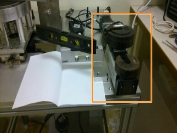
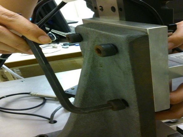
Use a spirit level to ensure that the load cell's surface is levelled.
-
Books or other objects can be used to help level the mount and load cell.
-
-
-
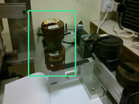
Add weights onto the actuator to act as counterbalance to any weights added to the load cell during calibration.
-
-
-
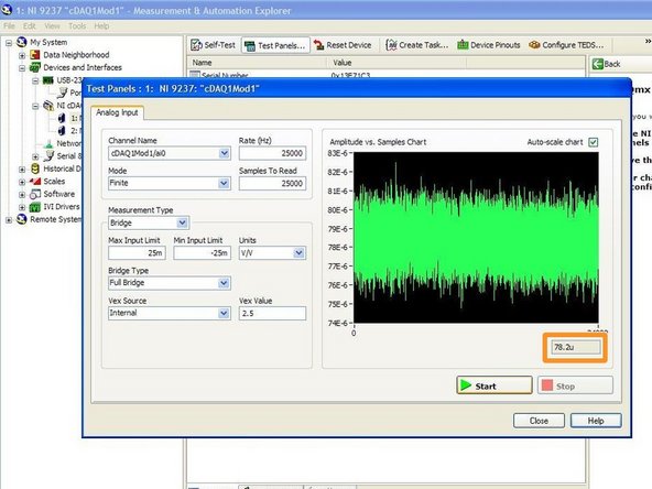
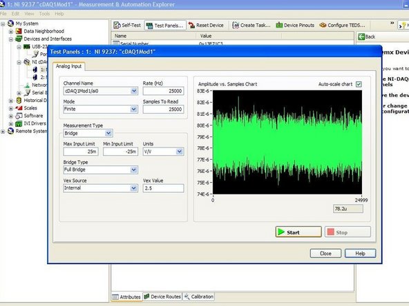
Using the MAX software, obtain 400 values of the voltage output when the load cell is unloaded (no load)
-
400 values are taken to limit the error bound on the estimate to 5%
-
-
-
Add weights to the load cell incrementally and obtain 400 voltage readings at each weight. Take at least 5 different readings to ensure accuracy of the load cell.
-
-
-
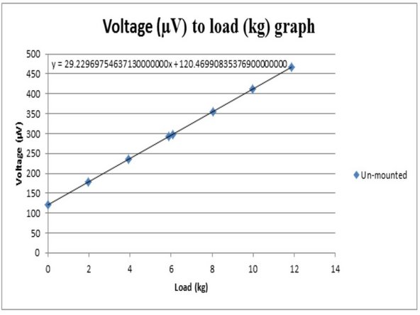
Using the values obtained, plot a voltage to load graph.
-
-
-
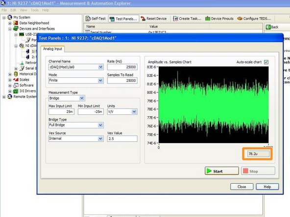
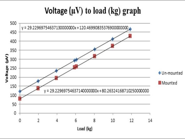
Once again, obtain 400 readings from the load cell after it has been mounted back to its usual position.
-
-
-
With the new voltage value at zero load, shift the graph to get final "a" and "c" values for the y=mx+c graph.
-
The gradient of the graphs should be the same as the load cell should measure the same corresponding change in voltage output with varying loads.
-
The voltage output at zero load will be different due to small changes in mass distribution of the materials in the load cell when it is lying flat and when it is upright.
-
-
-
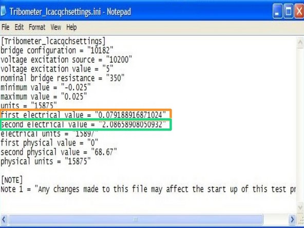
Input the first electrical value based on the voltage at zero newtons load.
-
Input the second electrical value based on the voltage at 68.67N load, which is also the highest frictional force the tribometer is specified to work at.
-


Cancel: I did not complete this guide.
One other person completed this guide.