
-
-
Using a venier caliper, measure the diameter (for a cyclindrical pin) or length of one side (for a square pin) of the pin sample.
-
For a more accurate value of diameter/width, measure the pin sample twice at two different points before taking its average.
-
The diameter/width values will be used as one of the input parameters in the production test screen later.
-
-
-
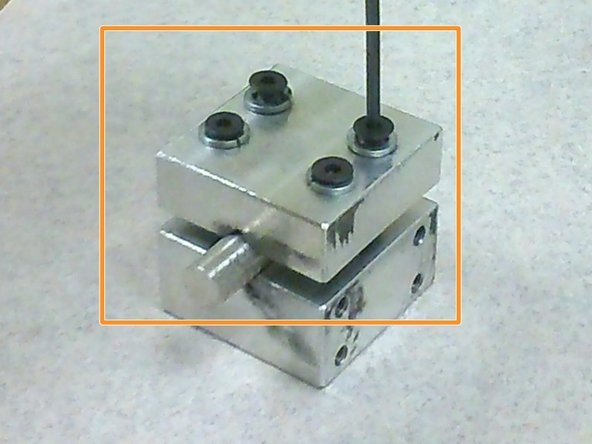
Place the pin sample into the groove.
-
At least half of length of the sample should be within the sample holder to minimise bending of the pin sample during wear testing.
-
-
-
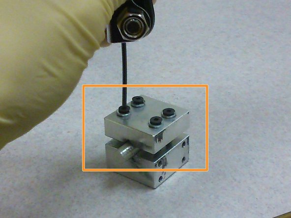
Using an allen key, tighten the two screws closer to the bottom of the sample holder.
-
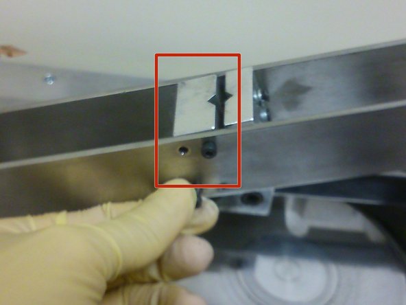
The two screws have to be tightened concurrently so that the two halves of the sample holder would be parallel to one another.
-
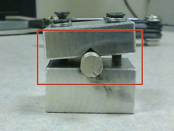
If the two halves are not parallel to each other (as shown in picture with red square), the sample holder would not be able to fit onto the cantilever beam.
-
-
-
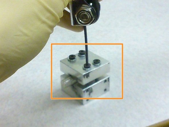
Use an allen key to tighten the remaining two screws.
-
If the sample is short and does not fill up the entire groove of the sample holder, ensure that the remaining screws are tightened to at least the same distance as that of the first two screws.
-
-
-
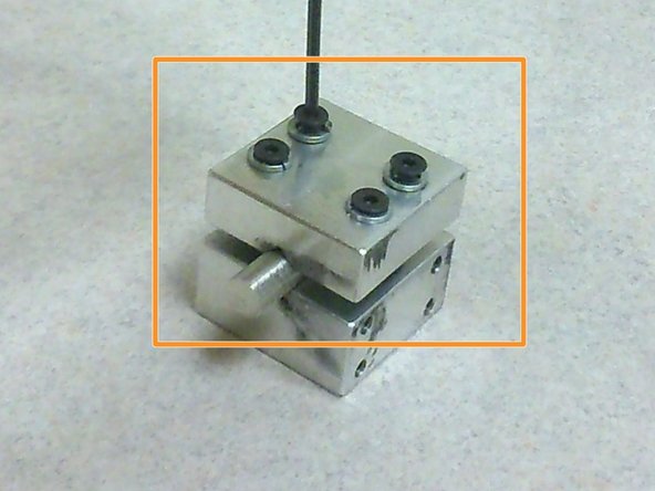
Using an allen key, secure the sample holder onto the cantilever beam using four M3 screws on the side of the cantilever beam facing the user.
-
As the sample holder is not symmetrical, ensure that the longer half of the sample holder is closer to the pivot of the cantilever beam where the inclinometer is located.
-
It is possible to secure another four screws on the side of the cantilever beam facing the load cell but doing so may cause the load cell to give an inaccurate reading (since the force is concentrated on where the screws are). Therefore, the sample holder is only secured to one side of the cantilever beam.
-


Cancel: I did not complete this guide.
One other person completed this guide.