
-
-
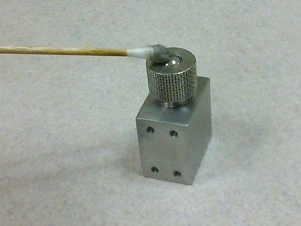
Using the microscope and LAZ EZ software, obtain (if required) the microscopic images of:
-
Ball surface before cleaning
-
Ball surface after cleaning with acetone
-
As it would be difficult to find the same ball surface if the ball is removed and placed back into the sample holder after capturing the images, simply keep the ball sample within the sample holder at all times instead and adjust the height required for image capturing accordingly.
-
-
-
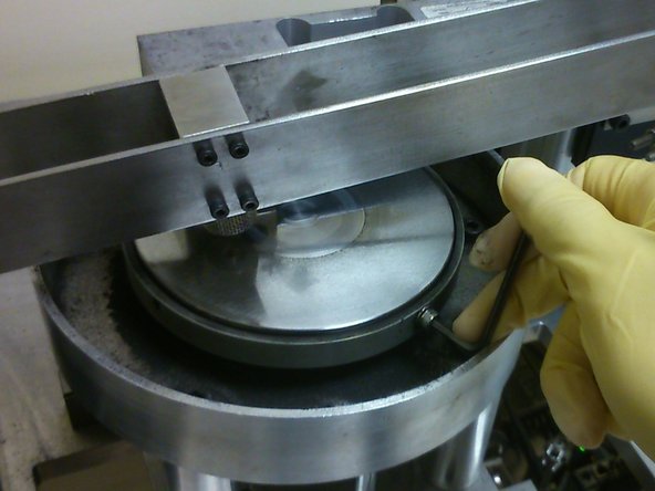
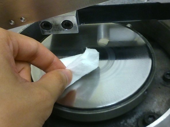
Using an allen key, secure the disk onto the disk holder by hand-tightening at least two M4 screws at opposite sides of the disk.
-
-
-
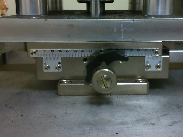
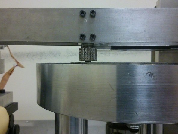
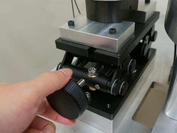
Use a torque wrench to turn the x-translation stage's knob to a suitable value.
-
Note that the larger the wear track radius, the lower the RPM required (RPM should never exceed 3000). However, a lower wear track radius would also increase the wear of the disk counterface.
-
Recall from the hardware guide that:
-
For ball specimen, Wear track radius = X + 32.5
-
Where X is value read from x-translation stage and S is sample size in mm.
-
-
-
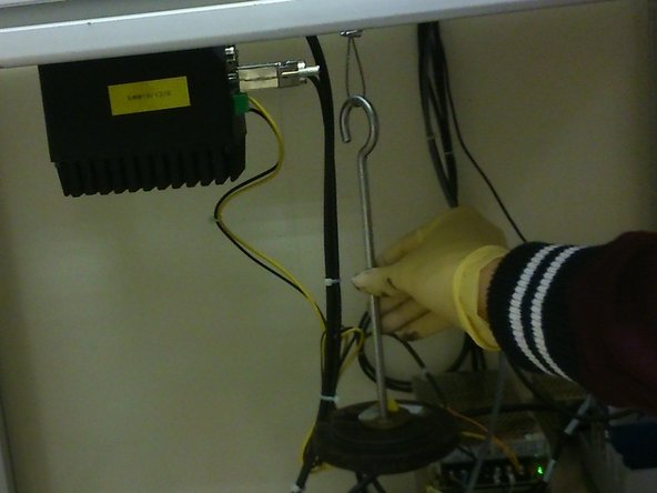
Using different masses and plasticine, load the hanging mass based on the normal load required.
-
Note that "Normal load" [N] = (22.0725 * "Hanging mass")[kg] - 12.37784676
-
-
-
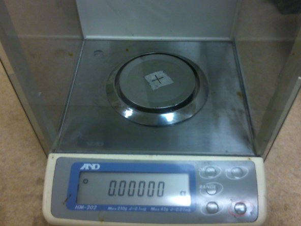
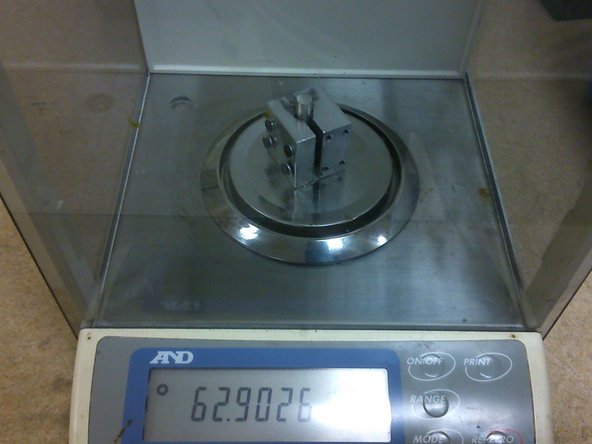
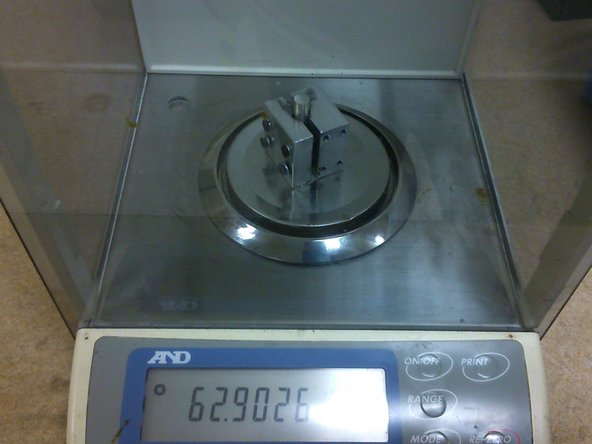
Always place the sample on the same spot on the weighing scale. Markings could be made on the weighing scale as shown in the picture.
-
-
-
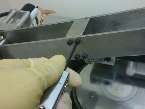
Use an allen key to hand-tighten four M3 screws on the side of the cantilever beam facing the user.
-
-
-
Ensure that the beam is as horizontal as possible by adjusting the height of the pivot.
-
This step is done in preparation of the zero-ing of inclinometer reading during the next step.
-
-
-
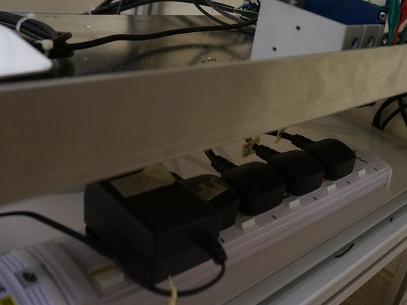
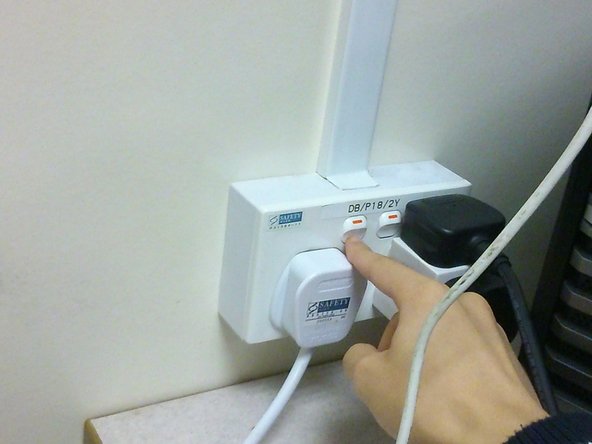
The multiple power plugs from the tribometer are linked to one another using an extension cord. Simply turn on the power supply to the extension cord to turn on all the power plugs.
-
-
-
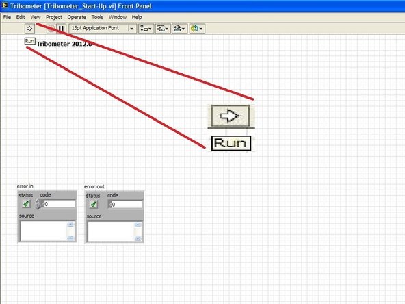
Desktop -> NUS_Tribometer 3 -> Tribometer_Start-Up.vi -> Run
-
-
-
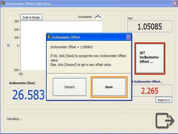
Click the "GET Inclinometer Offset" button.
-
When the Inclinometer Offset window appears, click "Save"
-
This would allow the system to collect 50 readings from the inclinometer which when averaged would give the zero-ed angle.
-
-
-
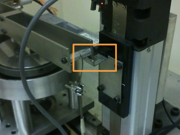
Place the end of the cantilever beam on the edge of the actuator's arm.
-
Doing so would prevent the cantilever beam from activating the load cell while it is still moving downwards onto the disk later, hence ensuring that the data collecting only begins when the sample is in contact with the disk counterface.
-
-
-
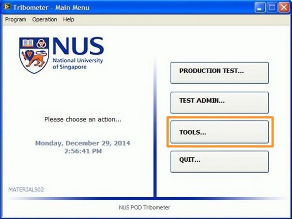
Click "PRODUCTION TEST" from main manu after exiting the "Tools" window
-
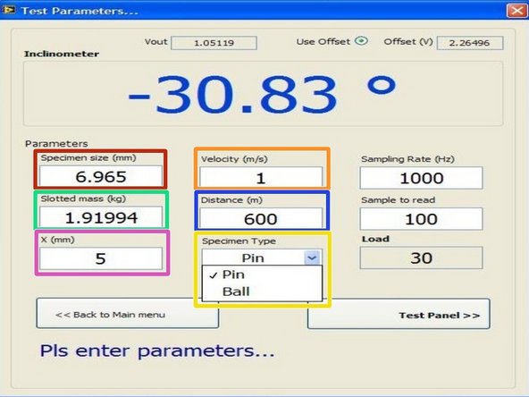
Update parameters accordingly:
-
Specimen Size (mm) - Diameter of ball sample
-
Velocity (m/s) - velocity required for wear test
-
Slotted mass(kg) - hanging mass in kg (Load on sample in Newtons would be computed based on this parameter and reflected on the same window)
-
Distance (m) - distance required for wear test
-
X (mm) - value of x-translation stage (RPM required by the motor would be computed based on X and velocity)
-
Specimen Type - Ensure that "Ball" is selected
-
-
-
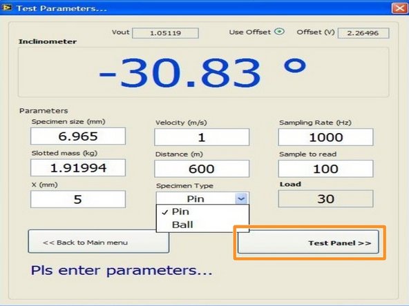
Click the "Test Panel" button at the bottom right of the production test window.
-
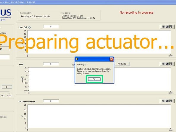
The actuator would be started up and moved to its home position. Click "OK" when prompted to allow actuator movement.
-
-
-
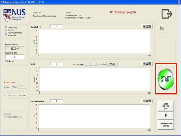
Click the green "START" button to begin the wear test.
-
The sequence of events that would follow the clicking of the button are:
-
The motor will begin accelerating to the RPM required.
-
After the motor maintains an RPM within the set-point percentage for a few seconds, the actuator would begin lowering the cantilever beam.
-
The sample would come in contact with the disk and the cantilever beam would move and come into contact with the load cell.
-
3 seconds after contact with the load cell, data recording begins.
-
After the sample has finished moving through the distance specified, the actuator would lift the cantilever beam back to its home position and the motor would then decelerate back to rest.
-
-
-
Always place the sample on the same spot on the weighing scale. Markings could be made on the weighing scale as shown in the picture.
-
Mass loss can be obtained from the difference in mass before and after wear test.
-
-
-
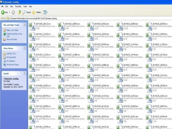
The wear test results can be found in the testlog. It is located at C:\Program Files\National Instruments\LabVIEW 2012\Tribometer_testlog
-


Cancel: I did not complete this guide.
One other person completed this guide.