-
-
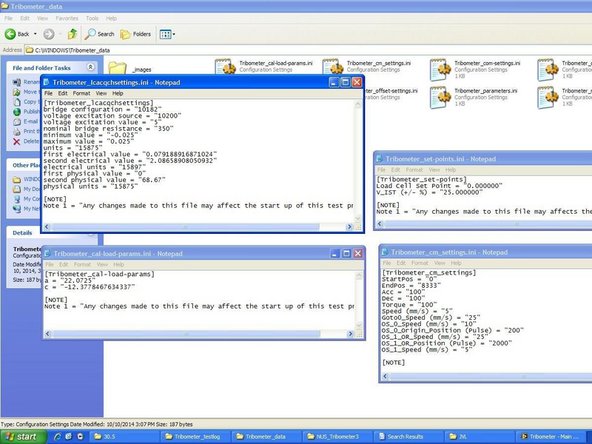
The tribometer data folder contains notepad files which controls the different settings of different components of the tribometer.
-
-
-
While most of the notepad files exists to facilitate the programming and integration of data from the tribometer and should not be edited, four files can be edited by the user for calibration and troubleshooting purposes. These four files will be elaborated on in the following steps.
-
-
-
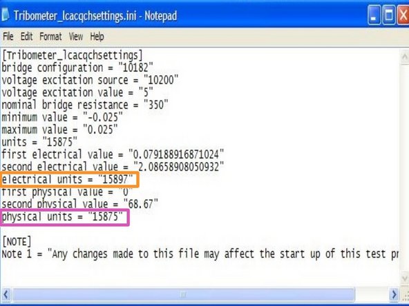
This file controls the load cell's settings. "bridge configuration" to "units" are parameters used during the installation of the load cell while "first electrical value" to "physcial units" can be edited by the user.
-
This file should only be used for calibration purposes, following the instructions from the load cell calibration guide.
-
The parameters to be edited are detailed below:
-
"electrical units = 15897" means that the electrical values to input are to be in units of millivolts
-
"physical units = 15875" means that the physical values to input are to be in units of newton
-
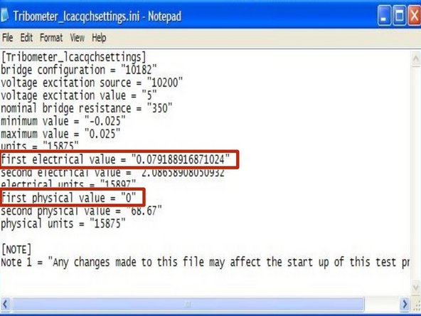
"first electrical value" is the value of voltage (in mV) corresponding to the amount of load (in newton) in "first physical value". In the example shown, a 0.0792mV voltage is read from the MAX software when there is 0N of load on the load cell.
-
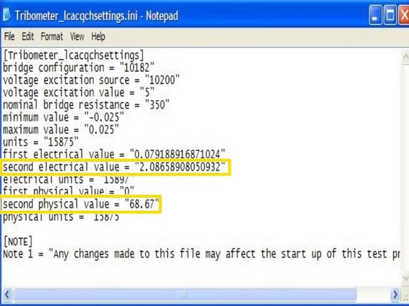
"second electrical value" is the value of voltage (in mV) corresponding to the amount of load (in newton) in "second physical value". Together with the first values, these second values, when plotted on a graph, gives the rate of change of voltage when load changes. This would enable the user to calibrate the load cell accurately.
-
-
-
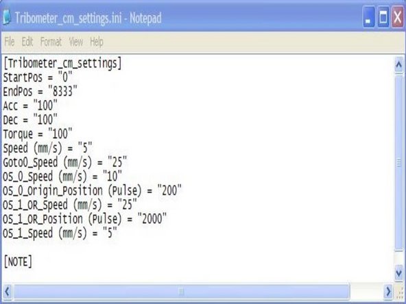
This file controls the settings of the actuator.
-
The different parameters control the start/end position, speed, and acceleration of the actuator.
-
The "OS_0_Origin_Position (Pulse)" parameter is used in the troubleshooting of the stuck actuator. Refer to troubleshooting guides for more information.
-
-
-
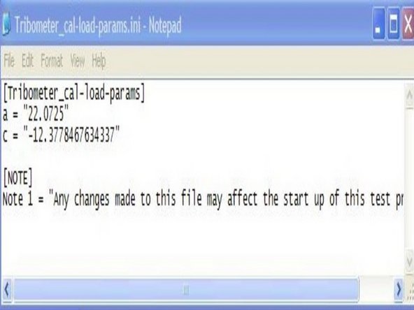
This file controls the hanging mass to normal load calculations done on the production test window. The program uses the y=mx+c relationship between hanging mass (kg) and normal load (N) to compute the normal load based on the hanging mass input.
-
The relationship between hanging mass and normal load can be calibrated with the help of the load cell and the calculations for their graphical relationship can be found in the "Lever Calculations" file on the computer.
-
-
-
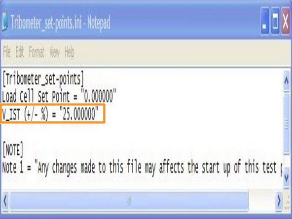
This file controls the set point at which the actuator is lowered. The actuator will only lowered during wear test when the RPM of the motor reaches within a certain percentage difference from the required RPM for a few seconds. Using this file, the percentage difference can be altered by the user.
-
This function is especially useful when running the motor at extremely low RPM (100 RPM or so during ASTM tests) as the the motor would not be able to maintain the required RPM for more than a few seconds.
-
The percentage difference can be set using the "V_IST (+/- %)" parameter and after changing and saving the file, the value can be seen at the top of the test interface.
-