
-
-
The test interface allows the user to control the motor to conduct wear testing.
-
-
-
Desktop -> NUS_Tribometer 3 -> Tribometer_Start-Up.vi -> Tribometer Front Panel -> Run
-
-
-
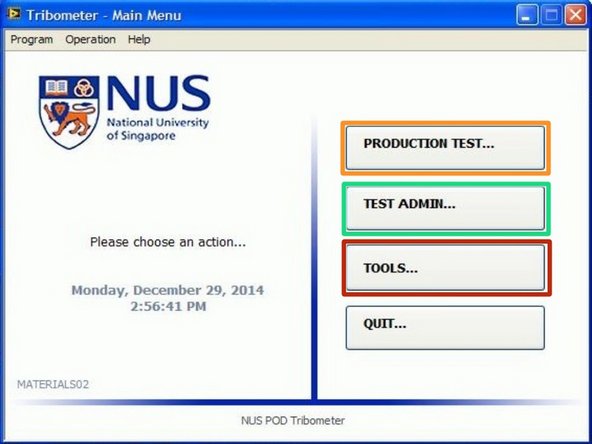
The main manu has the following three options:
-
"PRODUCTION TEST" - directs the user to the test parameters and subsequently test interface window
-
"TEST ADMIN" - directs the user to the system setup settings window
-
"TOOLS" - directs the user to the inclinometer reading window
-
-
-
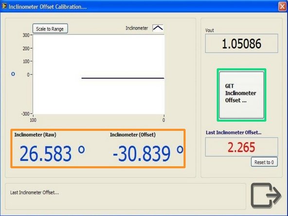
Clicking tools at the main manu opens up the inclinometer offset calibration window.
-
The raw and offset inclinometer-measured angle can be seen below the graph
-
Clicking "GET Inclinometer Offset" would prompt the collection of 50 readings from the inclinometer which average would correspond to zero-ed angle.
-
Ensure that the sample is resting on the disk counterface while zeroing the inclinometer.
-
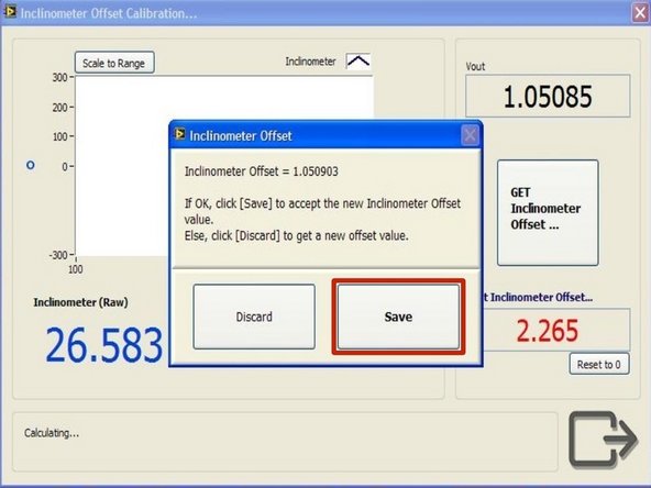
Do save, instead of discard, the calibrated offset after the prompt to do so appears.
-
-
-
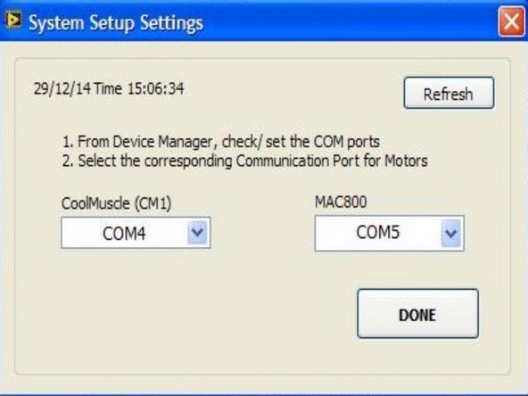
Clicking "TEST ADMIN" at the main manu directs the user to the system setup settings.
-
The COM ports for the actuator (CoolMuscle) and motor (MAC800) of the tribometer is selected using this window.
-
-
-
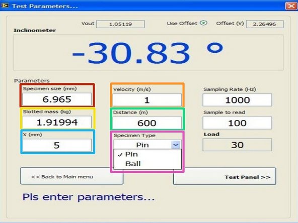
Clicking "PRODUCTION TEST" at the main manu directs the user to the test parameters window.
-
The following parameters for the wear test can be configured using this window:
-
Specimen Size (mm) - Diameter of ball sample or width of pin sample (more info on value of specimen size can be found in sample preparation guides)
-
Velocity (m/s) - velocity required for wear test
-
Slotted mass(kg) - hanging mass in kg (Load on sample in Newtons would be computed based on this parameter and reflected on the same window)
-
Distance (m) - distance required for wear test
-
X (mm) - value of x-translation stage (RPM required by the motor would be computed based on X and velocity)
-
Specimen Type - to select either "Ball" or "Pin" sample (calculation for RPM required differs based on samples)
-
-
-
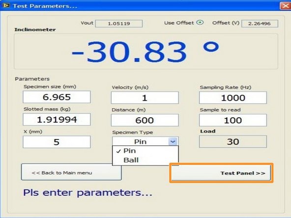
Clicking "Test Panel" on the test parameters window will direct the user to the test panel window.
-
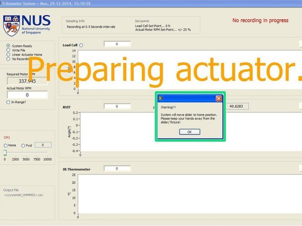
A prompt would appear every time the test panel is opened to alert the user that the actuator would reposition itself back to its home (or topmost) position.
-
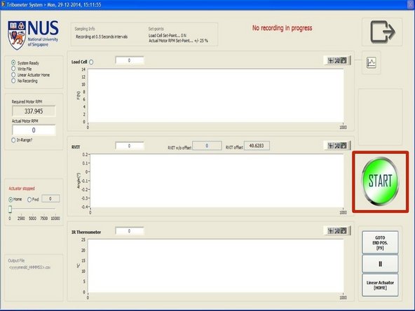
The test panel allows the user to start or end the wear test using the button on the right side of the window.
-
-
-
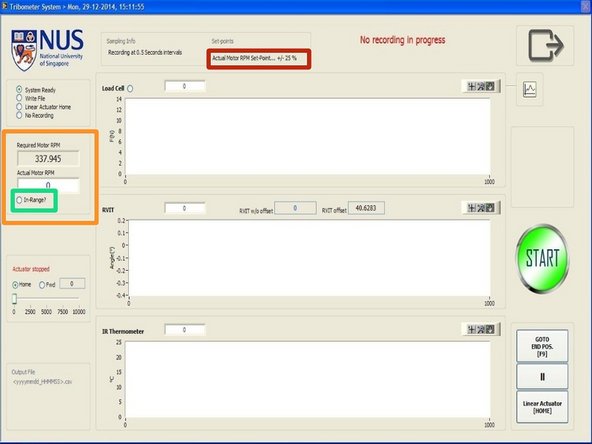
The required and actual RPM of the motor can be monitored on the left side of the window.
-
The in-range indicator would light up whenever the actual RPM is within a certain percentage of the required RPM
-
The percentage can be configured using the Tribometer_set-points.ini file. More info can be found in the Tribometer data guide.
-
The percentage can be seen on the top of the window under "Actual Motor RPM Set-Point... +/- XX %, where XX refers to the percentage difference between the actual and required RPM.
-
-
-
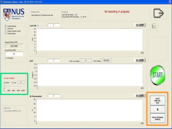
The position of the actuator can be controlled using the buttons on the bottom right hand corner of the window.
-
End position refers to the bottom-most position the actuator is programmed to go to while home position refers to its top-most position.
-
The position can only be controlled when the motor is not running.
-
The slider bar on the left of the window reflects the movement of the actuator during wear test while the motor is running.
-
The actuator is programmed to only start moving downwards when the 'In-range' indicator is lit for more than 5 seconds.
-
-
-
The data collected by the test panel would be written onto a excel file saved into the testlog.
-
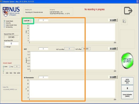
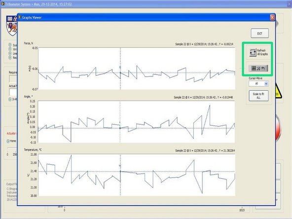
The various output data (force from load cell, angle from inclinometer, and temperature from IR thermometer) could be monitored through the three graph areas in the centre of the window.
-
The indicator light beside the word 'Load Cell' will be lit whenever a non-zero force is detected on the load cell.
-
Data collection will only begin 3 seconds after the indicator light remains lit.
-
-
-
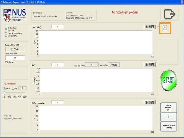
The data from the various sensors can be monitored while wear test is ongoing.
-
Clicking the graph icon above the 'Start/End' button will open up the 'Graphs Viewer'
-
The graphs can be refreshed and the tools under the refresh button can be used to monitor the data output accurately.
-


Cancel: I did not complete this guide.
One other person completed this guide.