
-
-
The load cell used on the tribometer is a model 1042 low profile aluminium load cell from vishay precision group.
-
The load cell measures the frictional force on the sample during wear testing by measuring the force exerted on it by the cantilever beam at the location the sample holder is located at.
-
-
-
The load cell force sensor is located beside the cantilever beam where the sample holder is. During operation, the cantilever beam should be parallel and in contact with the entire length of the force sensor.
-
-
-
The tribometer is programmed to start collecting data from the load cell, inclinometer, and IR thermometer after the load cell experiences a non-zero force for three seconds.
-
This means that the user can 'trick' the tribometer into taking readings even when the motor is not running by applying a force on it and removing it after three seconds. (Important fact for load cell calibration)
-
Likewise, the user can 'trick' the tribometer into not taking any readings even when the motor is running by simply not applying a force on the load cell. (Important fact for grinding/polishing of disk)
-
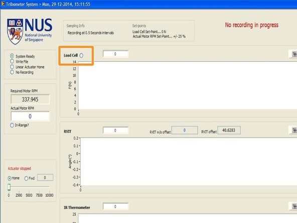
If a non-zero force is detected by the load cell, the indicator beside the load cell will be lighted up.
-
-
-
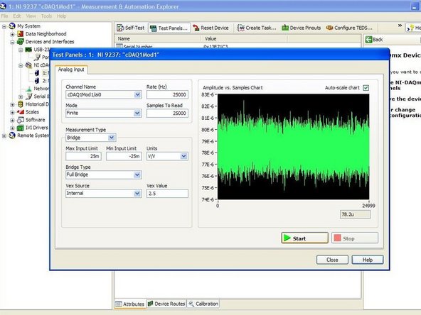
The voltage output of the load cell can be monitored using the "Measurement and Automation Explorer" software on the computer. More information on how to do so can be found in the "Measurement and Automation Explorer (MAX)" guide.
-
-
-
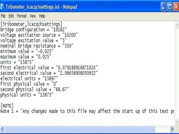
The configuration or settings of the load cell could be modified under the "Tribometer_lcacqchsettings.ini" file in the "Tribometer_data" folder on the desktop. More information on changing the settings within can be found in the load cell calibration guide.
-


Cancel: I did not complete this guide.
One other person completed this guide.