
-
-
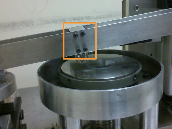
The inclinometer is located at the pivot of the cantilever beam and measures the angle at which the cantilever beam is tilted at.
-
The change in angle before and after wear testing could be used to compute the change in height (and therefore mass) of the samples.
-
The cantilever beam is used to hold onto the sample holder and would be lowered by the actuator onto the rotating disk counterface during wear testing.
-
-
-
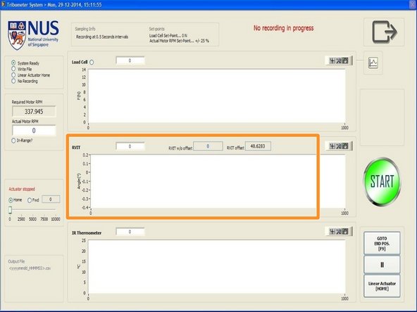
The inclinometer can be zero-ed using the "Tools" option at the main menu window. More details will on inclinometer zeroing can be found in the test interface guide.
-
The inclinometer has to be zeroed before every test so that all changes in angles will begin at zero degrees.
-
-
-
Readings from the inclinometer are one of the data recorded during wear testing alongside force and temperature readings.
-
-
-
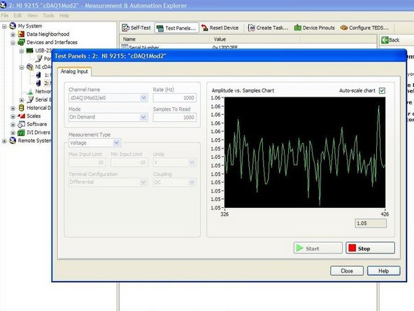
The raw data of the inclinometer, or voltage output of the inclinometer, can be motinored using the "Measurement and Automation Explorer" software on the computer. More information on how to do so can be found in the "Measurement and Automation Explorer (MAX)" guide.
-
-
-
The sample holder can be secured onto the cantilever beam using eight M3 screws, with four on each side of the cantilever beam. However, only four screws on the side of the cantilever beam facing the user would be used as the other four may act as force concentrators on the load cell and cause inaccurate readings.
-


Cancel: I did not complete this guide.
One other person completed this guide.